Circular Saw Reverse Engineering & CAE Analysis
Yale University – Computer-Aided Engineering
Product Reverse Engineering Project
Tools: SolidWorks, Motion Analysis, FEA, GD&T, CAM Simulation
Project Overview
This project focused on the reverse engineering and computer-aided engineering analysis of a commercial Ryobi circular saw. The objective was to disassemble an existing consumer power tool and reconstruct it digitally from the ground up, producing a fully constrained CAD assembly suitable for motion simulation, structural validation, and manufacturing analysis. The system was modeled to reflect realistic part interactions, tolerances, and drivetrain behavior, with particular emphasis on motor torque transmission through the rotor, gear train, and blade.
System Modeling & Assembly
All major components were modeled in SolidWorks and assembled using concentric, coincident, lock, and gear mates to accurately represent the physical constraints of the system. The final assembly reflects realistic degrees of freedom and captures the mechanical relationships between the rotor, fan, gears, shaft, and blade. A motion study was performed using the rotor as the driver component to simulate motor output. A constant rotational input was applied, and angular velocity and linear displacement were tracked at the blade edge to verify pure rotational motion and correct drivetrain behavior.
Rotor shaft technical drawing with functional GD&T for high-speed rotation

Von Mises stress distribution under simulated cutting load
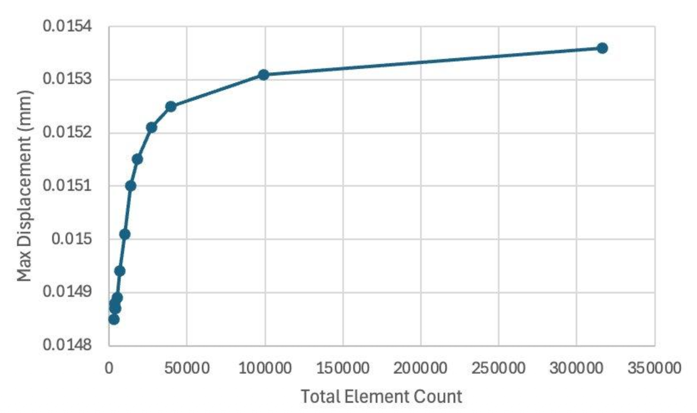
Mesh convergence study used to select element size for FEA accuracy

Fully constrained CAD assembly reconstructed from physical disassembly
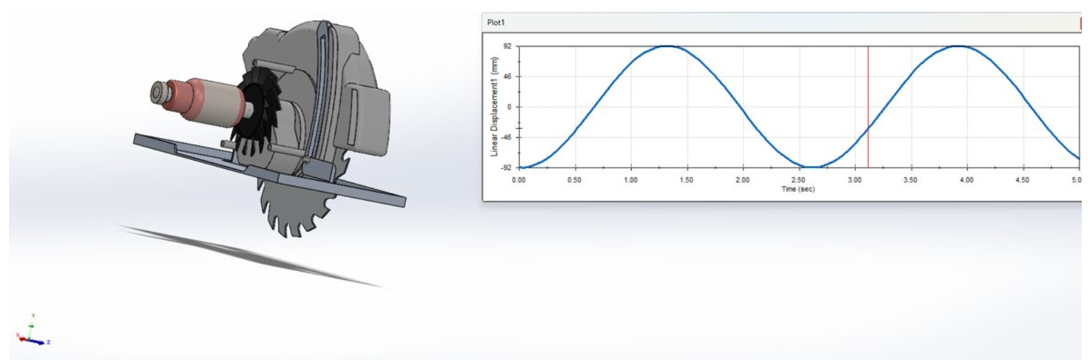
Linear displacement response of blade driven by motor input
Technical Drawings & Tolerancing
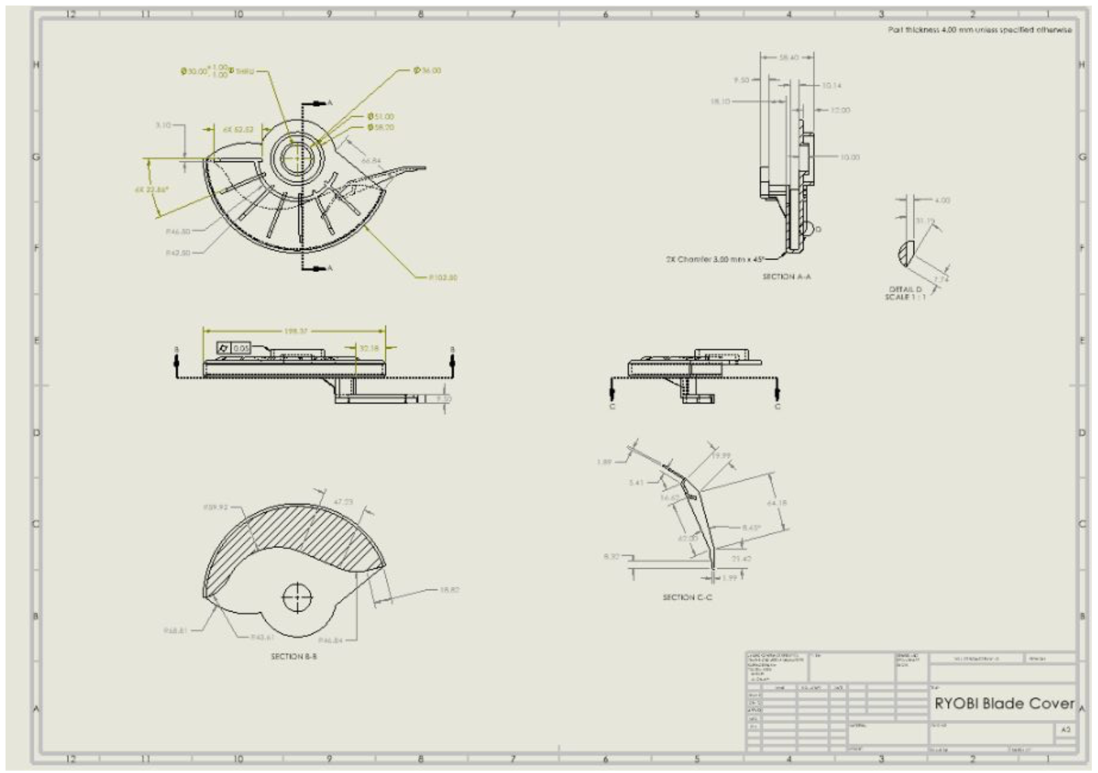
Two detailed technical drawings were produced to industry standards: the blade safety cover and the rotor shaft assembly. These components were selected due to their functional importance and geometric complexity.
Geometric dimensioning and tolerancing (GD&T) was applied to reflect real functional requirements. Total runout was specified on the rotor’s outer diameter relative to the shaft datum to control vibration in high-speed rotation. Perpendicularity was applied between the fan mounting face and shaft axis to prevent imbalance, and tight diameter tolerances were assigned to bearing and fan interfaces to ensure proper fit and assembly.
Structural Finite Element Analysis
Structural FEA was performed on the saw blade, the component expected to experience the highest loading during operation. A cutting load of 100 N was applied at the blade teeth to represent interaction with hardwood during use, while the blade was constrained at the central mounting location.
A mesh convergence study was conducted to determine an appropriate element size, balancing accuracy and computational efficiency. Convergence was observed at a maximum element size of 1.5 mm. Results showed a maximum deflection of approximately 0.015 mm, with stress concentrations at the blade hub and tooth roots, consistent with expected physical behavior. Failure analysis indicated a factor of safety of approximately 4 under operating conditions.
Manufacturing & CAM Considerations
Manufacturing feasibility was evaluated for the plastic blade guard using injection molding simulation. A two-gate configuration was selected to ensure complete mold filling across both the handle and circular shell. Flow analysis identified predicted weld lines, air traps, and localized sink marks, informing realistic manufacturing constraints and part geometry considerations.